With Swedish roots, Qvantum (based in Nyíregyháza), has decades of experience in the heat pump market. The company started as a family workshop and gradually grew into an international player. Qvantum was the company that was able to build heat pumps for all special cases where standard manufacturer products were not sufficient.
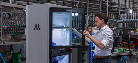
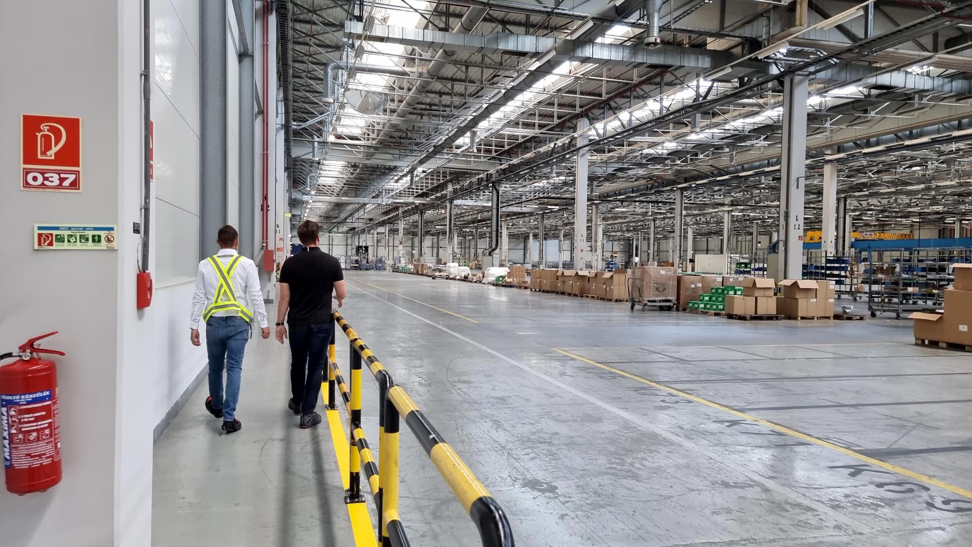
A few years ago, they started their large-scale European expansion, an important pillar of which is the capacity of their new production plant in Nyíregyháza. Taking over the former Electrolux plant in 2024 , they inherited not only the modern infrastructure but also local expertise: most of the people from the former team joined Qvantum. Building on their extensive experience in series production, their task now is to transition Qvantum's residential heat pumps into true mass production.
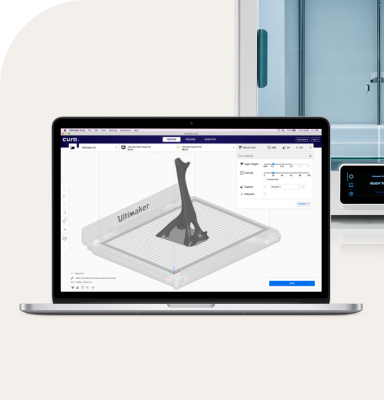
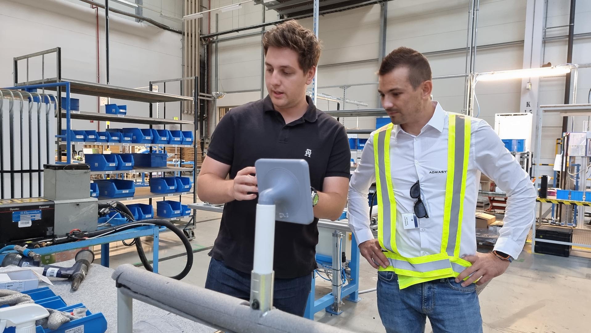
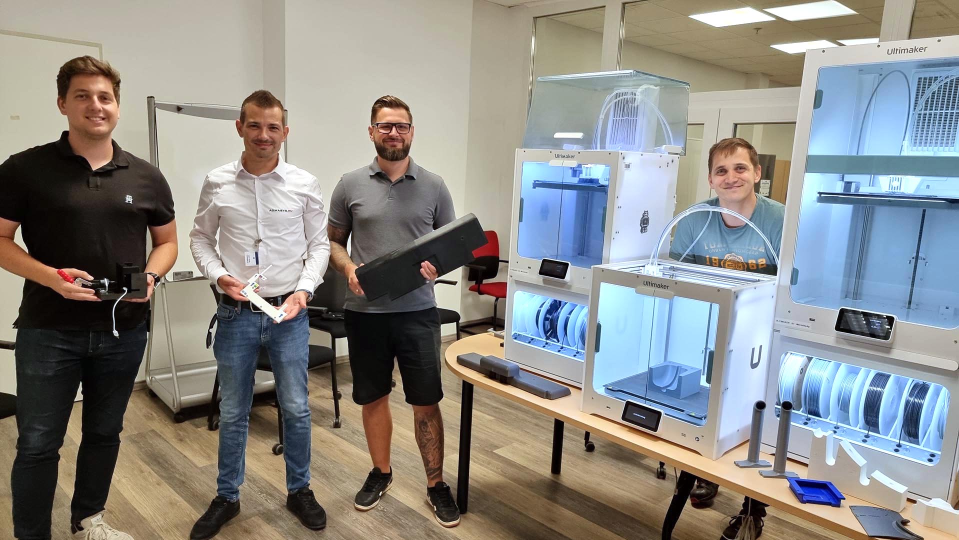
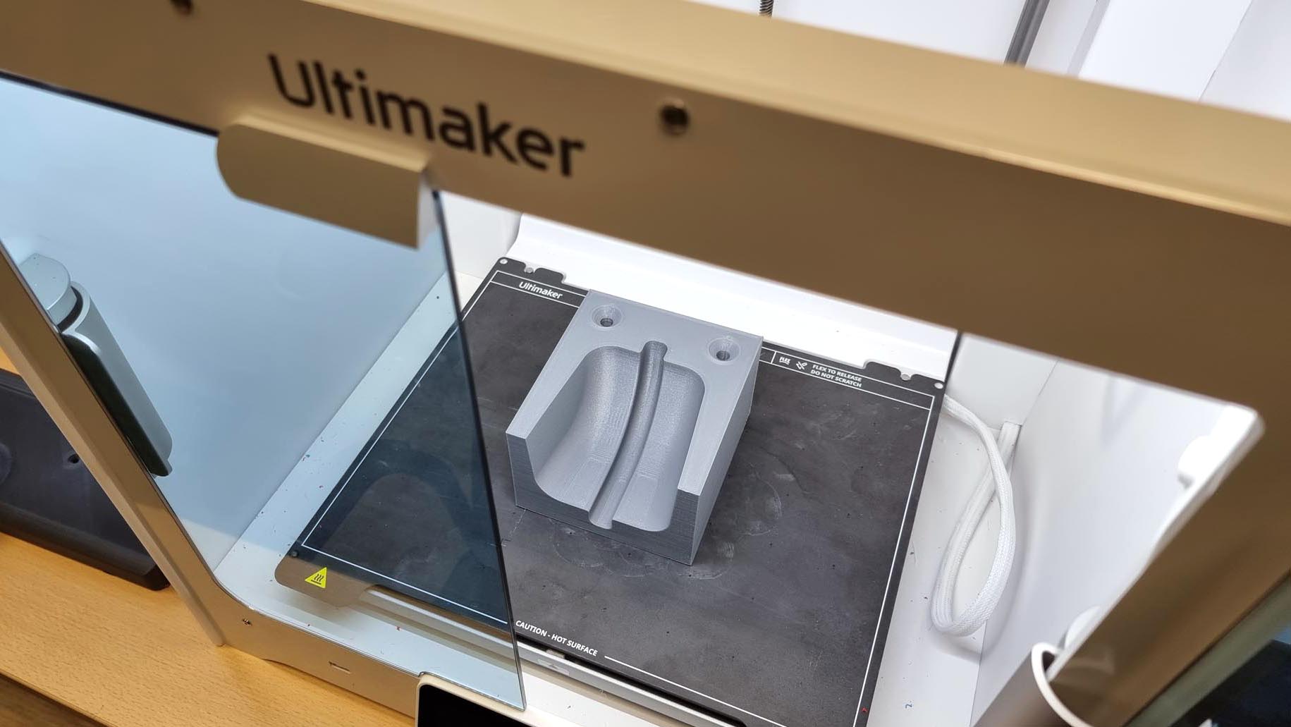
Qvantum's product development takes place in Sweden, while the design is examined in Nyíregyháza from the perspective of optimization for series production, so the final product may still take shape here. Since the fall of 2024, the domestic factory has been preparing for mass production of QA+QH residential air-to-water heat pump indoor units. Low-scale production has already started, and the QG model, which will be the company's smallest heat pump to date, is also planned to be introduced in the near future. Series production would not have been possible so quickly without 3D printers.