3D printing infill density: Optimizing strength and apeed

User Profile Image

Sara Wickstrom

September 17, 2025

Most 3D printing projects focus on external design, but the internal structure—specifically infill density—plays a pivotal role in determining the final product's performance.

Adjusting infill settings allows you to fine-tune a print's strength, weight, and material usage. Understanding how these settings interact is essential for achieving optimal results, whether you're creating prototypes or functional parts.

This guide explores how to leverage infill to balance structural integrity with efficiency, ensuring your 3D prints meet specific performance needs while minimizing waste and production time.

Understanding 3D printer infill and its importance

3D printer infill is a critical element for successful 3D printing. It's the internal structure that dictates how printed objects perform. Unlike traditional manufacturing, 3D printing allows for customizable internal structures, optimized for specific needs.

Infill refers to the internal lattice or pattern filling the hollow spaces inside a 3D printed object. This framework provides structural support, allowing control over weight, material use, and printing time. The infill acts as the skeleton, ensuring external walls keep their shape and the object withstands stress.

Infill density significantly affects the final characteristics of a printed part. Measured as a percentage from 0% (hollow) to 100% (solid), it directly impacts strength, weight, material consumption, and printing time. Understanding how to adjust infill density allows for creating parts that meet performance needs while minimizing waste and production time.

Material-specific strength vs. density

While infill percentages tell you how much plastic you’re putting inside a part, the material’s own mechanical and thermal traits ultimately decide how strong—or heat-resistant—that part will be.

The matrix below pairs common FDM polymers with the density ranges that typically maximise stiffness, plus a quick note on each material’s standout property.

Treat it as a reference when choosing between bumping up infill or switching to a different filament altogether.

Because stiffness varies by polymer, ideal densities shift accordingly.

Material Typical Infill Density for Stiff Parts Notes
PLA 20 – 30 % Easy to print; brittle; softens ≈ 60 °C
PETG 25 – 40 % Tough, slightly flexible; heat-resistant to ≈ 80 °C
ABS 30 – 50 % Higher temp tolerance (≈ 95 °C); needs enclosure to avoid warping
Nylon (PA-12/PA-6) 35 – 50 % Excellent impact strength; hygroscopic—dry before printing
Carbon-fiber–filled PLA/PETG 15 – 25 % Reinforced fibers boost stiffness, letting you lower density

*Figures assume 2–3 perimeter walls and a strength-oriented pattern (cubic, gyroid, tri-hex).

The right infill selection goes beyond structural considerations. Different uses need different approaches: a decorative vase might work with minimal infill, while a mechanical part under repeated stress requires a carefully chosen infill density and pattern.

This adaptability makes infill a powerful tool.

For a deeper dive, explore different infill patterns available in slicing software and their unique properties.

Exploring different infill patterns and their benefits

With a solid grasp of infill's importance, the next step is understanding the variety of patterns available. Each pattern offers unique advantages, making it crucial to select the right one for your specific project requirements.

Various infill patterns exist, each designed for specific printing challenges. Understanding their characteristics helps in selecting the best option.

Rectilinear infill, also known as the lines pattern, is a straightforward approach. This pattern creates parallel lines that alternate direction with each layer, forming a grid. While not the strongest, rectilinear infill prints quickly and uses material efficiently. It's suitable for prototypes and non-critical uses where speed is important.

Gyroid infill is a sophisticated pattern. This structure creates flowing, wave-like internal geometry that provides nearly equal strength in all directions. The gyroid pattern distributes stress evenly, making it suitable for parts experiencing forces from multiple angles. Also, gyroid infill tends to be relatively quiet during printing due to its smooth, continuous paths.

Concentric infill follows the contours of the object's outer perimeter, creating internal structures mirroring the external shape. This pattern works well for cylindrical or curved objects, maintaining the part's natural stress distribution. Concentric infill also provides controlled flexibility, making it suitable for uses needing some elasticity.

Cubic infill creates a three-dimensional grid structure that offers uniform strength. Unlike simple grid patterns providing strength in two dimensions per layer, cubic infill builds true 3D structural elements that can handle complex loading. This makes it a good choice for mechanical parts and functional components needing reliable performance.

Lightning infill prioritizes speed. This pattern strategically places material only where needed to support the outer walls, creating a structure resembling lightning bolts or tree branches. While lightning infill reduces material use and printing time, it reduces strength and should only be used for non-functional parts or rapid prototypes.

More information on lightning infill can help you decide if it's right for your project.

Choosing the best infill pattern for strength

When structural integrity is paramount, selecting the right infill pattern becomes crucial. While several patterns offer robust support, the optimal choice depends on the specific demands of your project.

When strength is the main goal, some infill patterns offer better performance. The best pattern depends on the specific loading conditions, but several patterns consistently provide good structural performance.

Cubic infill is a reliable choice. Its three-dimensional grid structure provides uniform load distribution, making it effective for parts experiencing complex stress. The cubic pattern's ability to maintain consistent strength makes it useful for mechanical components, tools, and structural elements.

Gyroid infill offers benefits for uses needing equal strength in all directions. The mathematical structure ensures consistent strength regardless of the direction of forces. This makes gyroid infill valuable for parts experiencing dynamic loading or stress from multiple directions. The pattern's geometry also tends to distribute stress more naturally, reducing stress concentration points.

Tri-hexagon infill combines the structural efficiency of triangles with the material efficiency of hexagons. This creates an internal structure that maximizes strength while minimizing material use. The triangular elements provide good compression resistance, while the hexagonal components offer good tensile strength. This combination makes tri-hexagon infill effective for parts resisting both compression and tension.

The best pattern also depends on infill density. Higher density percentages generally increase strength, but the relationship between density and strength varies among patterns. Understanding these relationships allows for achieving target strength while minimizing material use and printing time.

Optimizing print speed with the fastest infill patterns

While strength is often a primary concern, print speed can be equally important, especially for rapid prototyping or large production runs. Fortunately, certain infill patterns are designed to minimize printing time without significantly compromising structural integrity. For tips on further increasing your printing speed, see how to 3D print faster.

Speed optimization often involves compromises, and infill pattern selection is an effective way to reduce printing time without sacrificing functionality. The fastest patterns use simplified geometry and continuous printing paths that minimize printer head movement.

Lines or rectilinear infill is often the fastest due to its geometry and efficient paths. The pattern consists of parallel lines alternating direction, creating long extrusion paths that allow the printer to maintain speed. This simplicity reduces printing time, making lines infill a good choice for rapid prototyping and non-critical uses where speed is important.

Lightning infill is optimized for speed. This pattern places material only where needed to support the outer walls. Lightning infill can reduce printing time while using less material. However, this speed reduces structural integrity, making lightning infill suitable only for display models, prototypes, and non-functional uses.

Zigzag infill offers a balance between the speed of lines infill and slightly better strength. By creating continuous back-and-forth paths without lifting the print head, zigzag infill maintains speed while providing better structural performance. This pattern works well for parts needing some internal structure but not maximum strength.

Balancing infill density and print quality

Achieving the ideal 3D print involves more than just selecting a pattern; it requires fine-tuning infill density to strike a balance between strength, print quality, and material usage. Understanding how infill density affects these factors is essential for optimizing your results.

The relationship between infill percentage and print quality involves interactions between structural integrity, surface finish, material use, and printing time. Achieving good results requires understanding how infill density affects these factors.

Infill density affects strength. While higher percentages generally increase strength, this relationship isn't linear, and the point of diminishing returns varies depending on the pattern and loading conditions. For many uses, densities between 20% and 40% provide good strength-to-weight ratios while maintaining reasonable printing times and material use.

The infill overlap percentage setting controls how well the internal structure bonds with the outer walls. Proper overlap ensures the infill supports the perimeter walls, preventing delamination and improving part integrity. Insufficient overlap can lead to weak bonds, while excessive overlap can cause over-extrusion and surface issues. Most uses benefit from overlap percentages between 10% and 25%, depending on the material and printing conditions.

Don’t ignore wall count: two extra perimeters often add more strength than raising infill from 20 % → 30 %. Treat shells as the primary load path; infill is backup.

Surface quality also influences infill density. Low percentages can sometimes cause visible surface imperfections, particularly on large flat surfaces where insufficient internal support allows the outer walls to sag. High densities may cause surface bulging due to internal stresses during cooling. Finding the right balance ensures both structural performance and aesthetic quality.

Advanced infill techniques for optimal results

For those seeking to push the boundaries of 3D printing, advanced infill techniques offer a pathway to creating parts with exceptional performance and efficiency.

These methods provide granular control over material placement, allowing for optimized structures tailored to specific needs.

Variable infill density is a technique available in software. This allows different regions of the same part to use different densities, concentrating material where strength is needed while reducing it in less critical areas.

For example, a bracket might use high-density infill in stress-bearing regions while using minimal infill in decorative sections. This requires careful analysis but can result in material savings without compromising performance.

Adaptive infill adjusts infill density based on the geometric needs of different part regions. Areas with thin walls, overhangs, or complex geometry automatically receive higher density, while thick-walled regions use lower density to save material and time.

Specialized infill types offer benefits for specific uses. These patterns combine geometric principles to create internal structures optimized for particular loading conditions. Understanding when and how to apply these types can improve print quality, making the difference between adequate and good results.

But advanced tricks only help if the printer is dialled in - run through this quick checklist first:

  • Nozzle diameter ≥ 0.4 mm (or adjust line-width settings)
  • Flow/extrusion multiplier calibrated with a single-wall test cube
  • Minimum printable feature ≥ 1.2 × nozzle diameter
  • Bed level & first-layer height verified across the build plate
  • Filament dry (especially PETG, ABS, nylon)
  • Cooling-fan profile matched to the material
  • Firmware and slicer up to date

Conclusion

Remember that while theoretical knowledge is invaluable, practical experimentation remains key. Don't hesitate to print test specimens, iterate on your designs, and push the boundaries of what's possible with your 3D printer. As the technology continues to evolve, staying curious and open to new techniques will help you stay at the forefront of 3D printing innovation.

By applying the knowledge gained from this guide and continuing to explore new possibilities, you'll be well-equipped to tackle even the most challenging 3D printing projects with confidence.

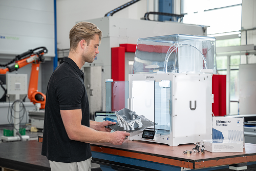
Advanced 3D printers like the UltiMaker S8 can expand your possibilities, whether you're creating rapid prototypes, end-use parts, or pushing the limits of additive manufacturing, the world of infill patterns offers a vast playground for optimization and creativity.

Further reading and resources

UltiMaker S6: Faster, smarter, more accessible.

Explore 3D printing with UltiMaker.

Request a quote