A NetFabb workshop convinced me that I can't live without this application. See why it's time to take another look at Netfabb.
Before Autodesk purchased Netfabb, I often used the free software to repair files, reverse engineer models, and to cut files into parts. While I still had my copy of Netfabb Basic on my computer, I could no longer freely recommend Netfabb to teachers who were new to 3D design and printing. Now a windows only application, the licensed version of Netfabb, while free to educators and students, was no longer available to those schools that were solely Mac-based. This would include the school where I taught for fourteen years.
Netfabb had been an important node in my workflow, so I installed Parallels (I might have done this so that I could run Rhino with Grasshopper too and installed Netfabb Standard 2018. I then attended a NetFabb workshop. I now wonder how I was so easily willing to give up this tool.
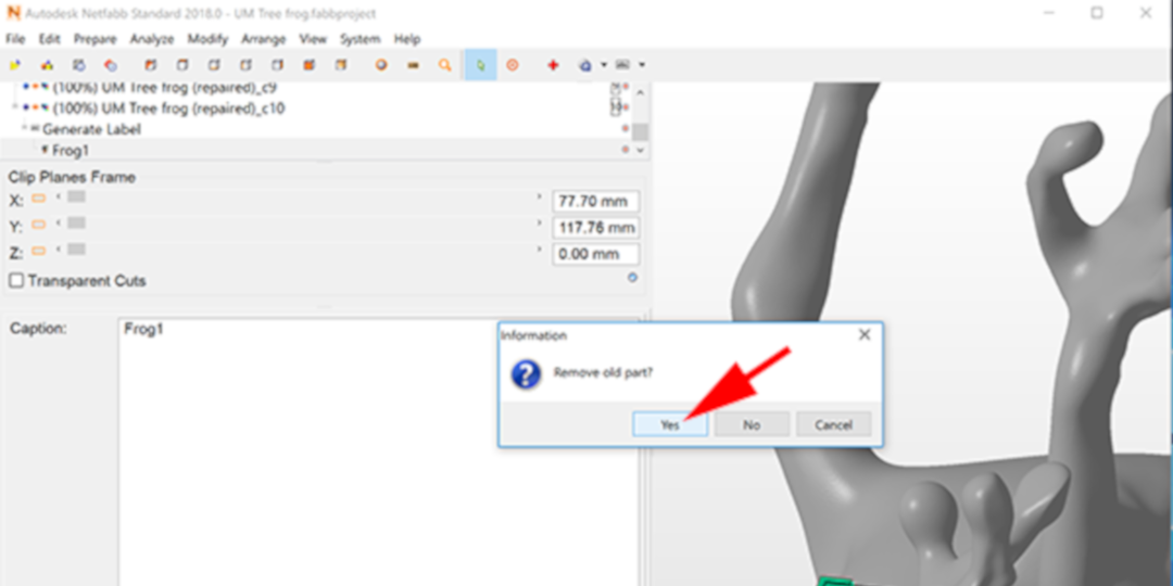
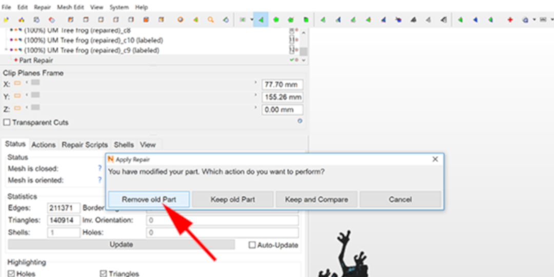
What can Netfabb do for you? Well, it first and foremost allows you to check and repair files. Bring in a file, see if there is an exclamation point in a triangle, and if so, click on the red cross button. The easiest repair and often the only one you’ll need is the default repair. Click on Execute the Repair, remove the old part, then export your repaired mesh, and print.
Recently I created a two color model of the Ultimaker robot in Fusion 360. The one thing I did not want to do was export the tiny white parts and the tiny black parts as individual STL files. My solution? Attach a .2 mm extruded plane to each of them, then export the two files as STLs, import into Netfabb and cut the plane off from each. Unlike Fusion 360, Netfabb doesn’t care if the parts are separate, it will still allow you to export them as a single STL file.
In the workshop I found that Netfabb can do much more to help your workflow. I also realized that there are other tools, like Meshmixer and Meshlab, that do similar things. I find Meshmixer a great tool, but not very intuitive, and my biggest complaint with Meshlab, is that it doesn’t support an undo command.
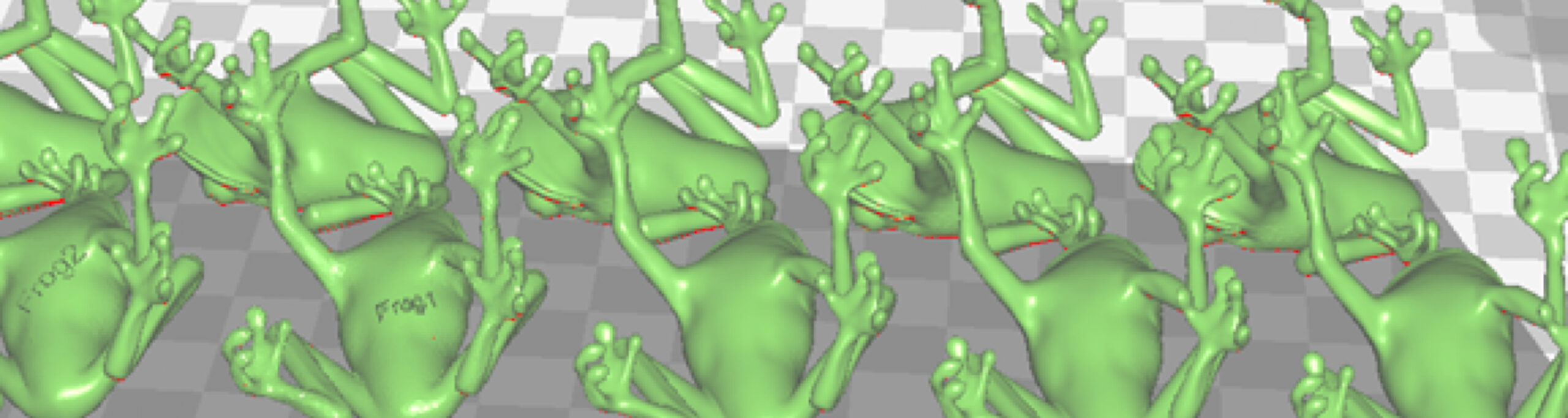
So what am I now doing with Netfabb? I’m duplicating my models, setting up the positions on the build plate, applying extruded or embossed text to the models, changing the mesh densities and exporting the group as a 3MF file.
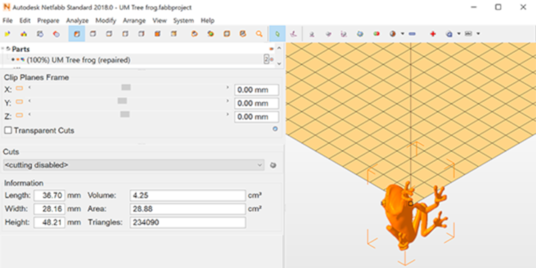
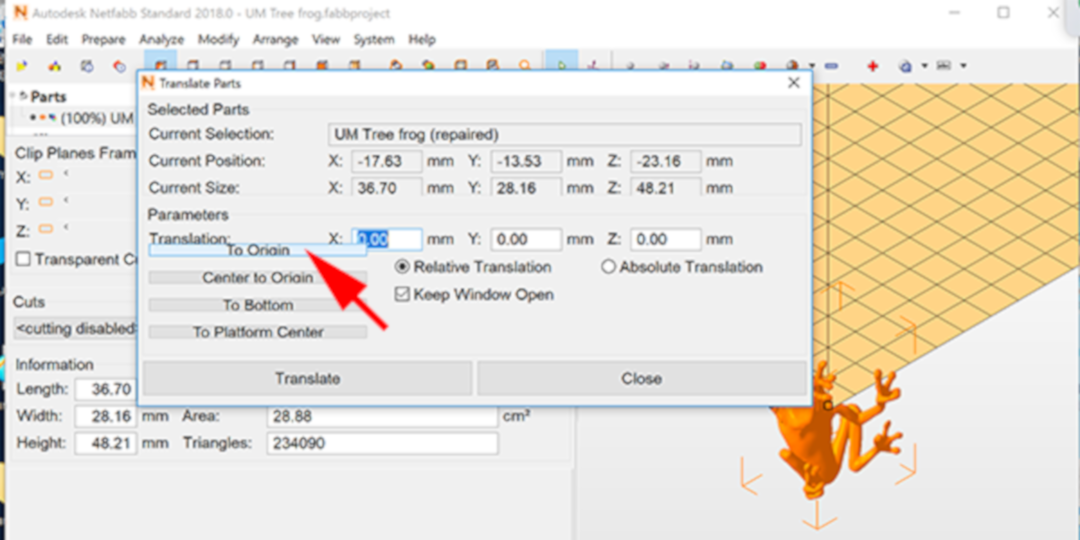
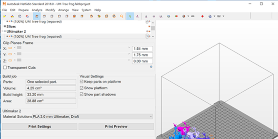
1. Import your STL file:
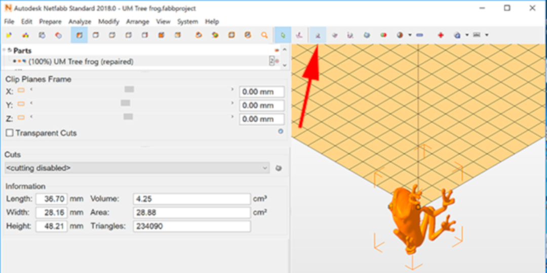
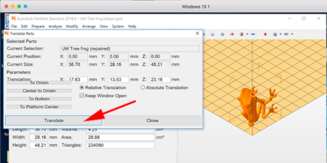
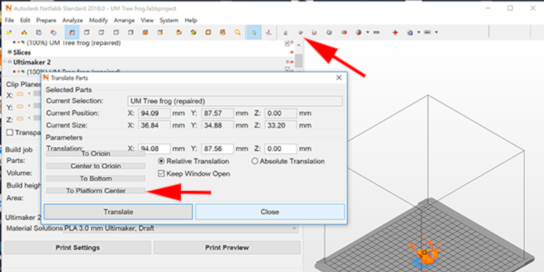
4. Click on the Translate button to accept the transformation:
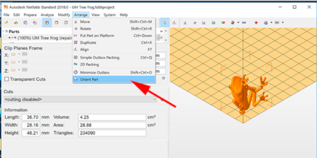
5. Select Arrange → Orient Part:
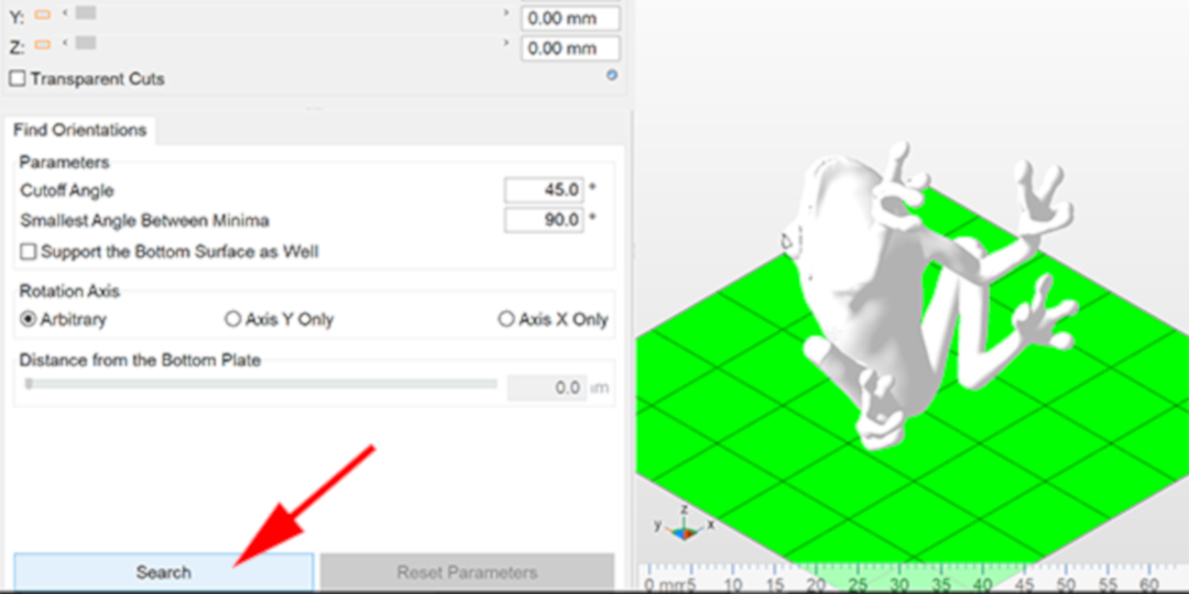
6. Click on the Search button. Netfabb will now start processing how your part can be oriented:
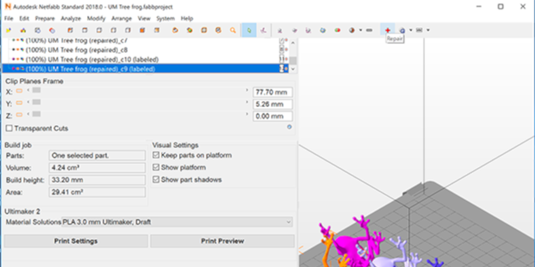
7. Netfabb has determined how the different orientations take different resources. Scroll through your options and find the balance between part strength and material usage.
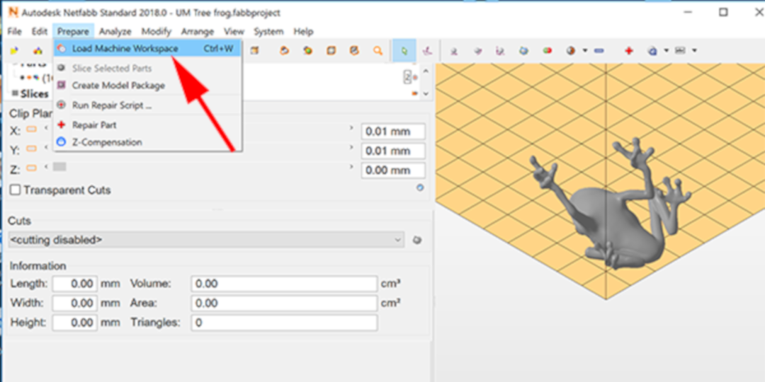
8. Under Prepare select Load Machine Workspace. Since you’re spending time arranging your part, you might as well have the proper buildplate to work with:
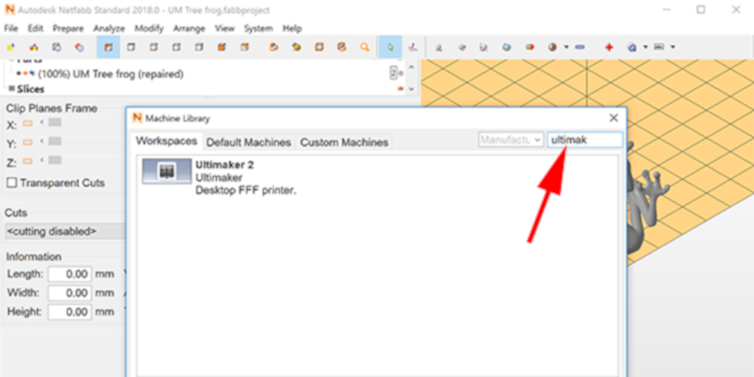
9. Start typing the company name and Netfabb will jump to that option. Then click on the selection on the left and press OK:
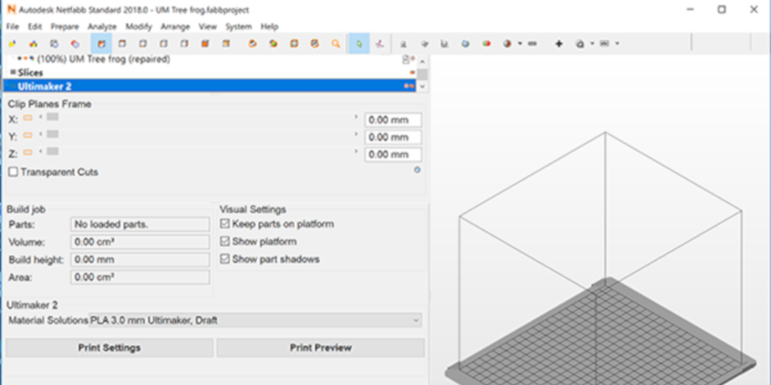
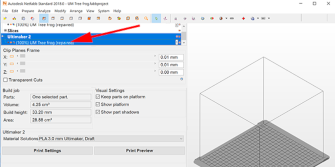
10. You have now loaded the buildplate, but your model seems to have disappeared. In the left panel, you need to drag your model onto the named workspace:
11. Select the Move Icon and move the model to the center of the buildplate by selecting to Platform Center:
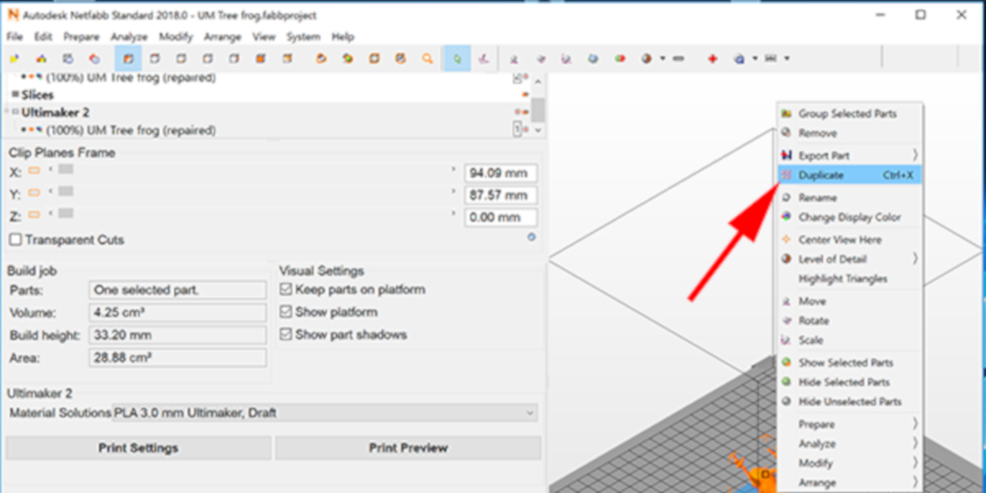
12. CTRL+click on the model and select Duplicate or type Ctrl+X to bring up the dialog window:
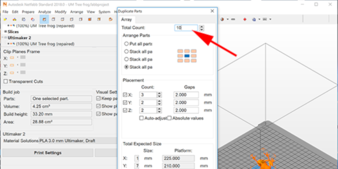
13. Determine how many copies you want and select how you prefer them to be arranged, then click on the Duplicate button:
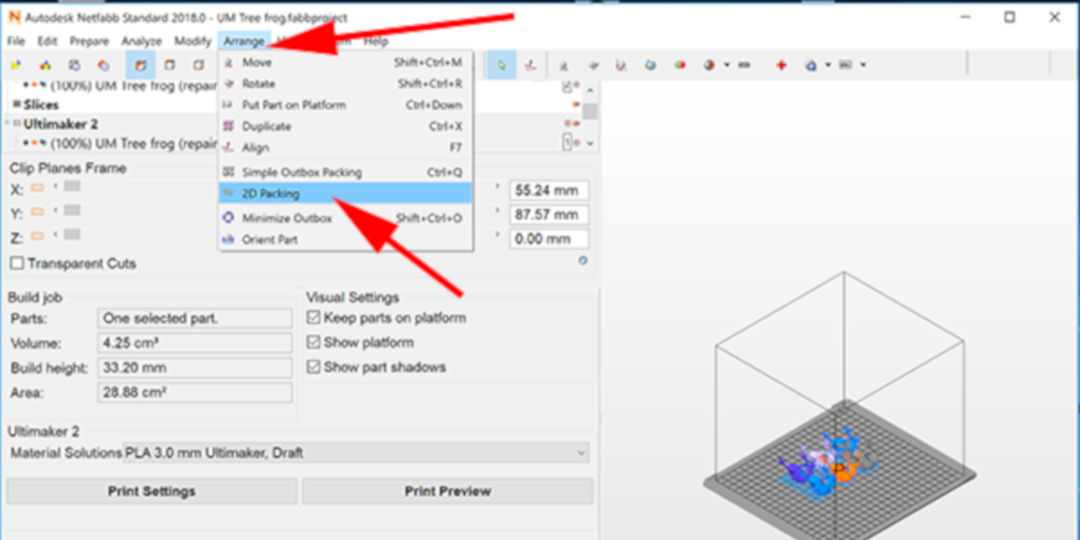
14. Now select Arrange→ 2D Packing to efficiently place the models across the buildplate:
15. Click on the Move Icon. Select all the models and translate them to the center of the buildplate:
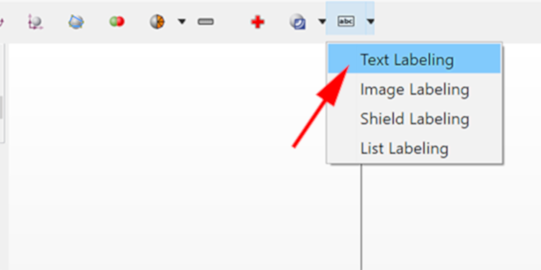
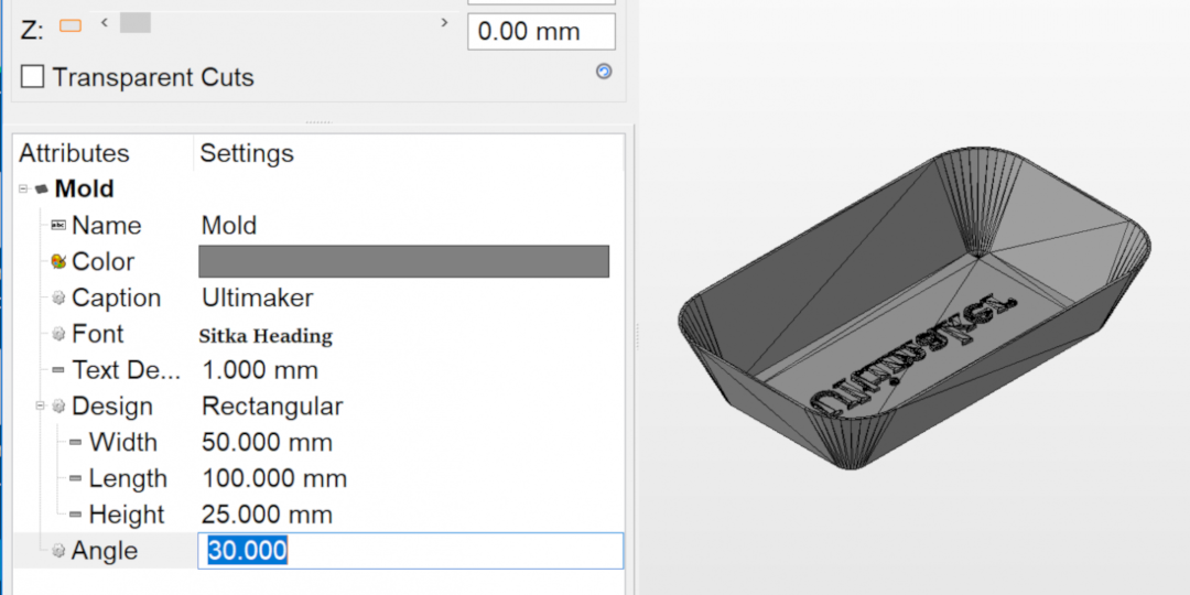
16. Next is one of my favorite actions: Text Labeling. Netfabb will take your text and automatically wrap it over your mesh. Under the abc Icon, select Text Labeling:
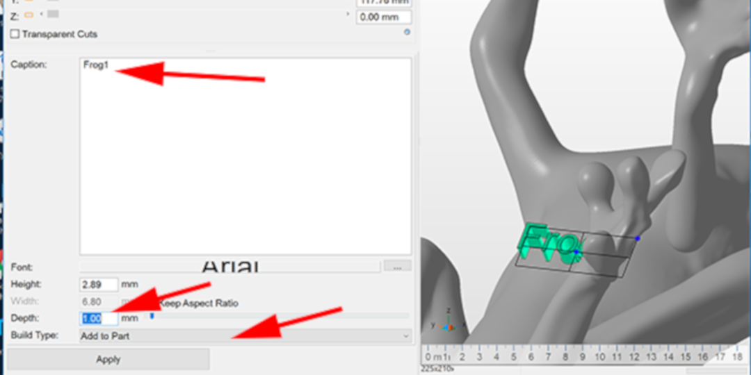
17. In the caption box, type the text you want to apply to your model. Now you may just want to add decorative text, but Netfabb makes it really easy to apply text, that you might want to consider applying codes to your models that identify the iteration. Maybe you are developing a project and you want to test options. You could print your model and write the code on the bottom with a sharpie, but by applying the text to the model in Netfabb, you don’t have to worry about smearing the ink. The trick here is that you need to keep track of what your codes mean. I would suggest using a spreadsheet to keep track of codes and changes to models.
Once you type your text, figure out if you will extrude or emboss. 1mm is a printable extrusion for text in most orientations. Adjust the location and size of the text in the window on the right and when you are satisfied, click Apply:
19. Select one of your coded models and hit the Repair Icon:
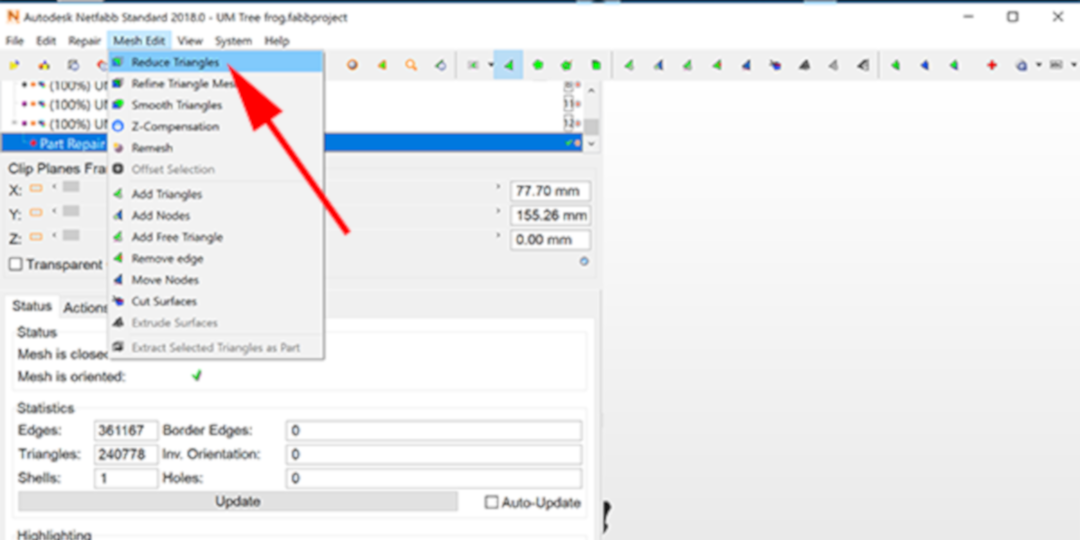
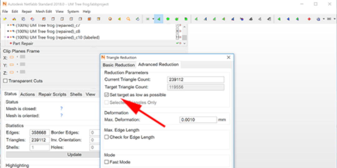
20. Select Mesh Edit → Reduce Triangles:
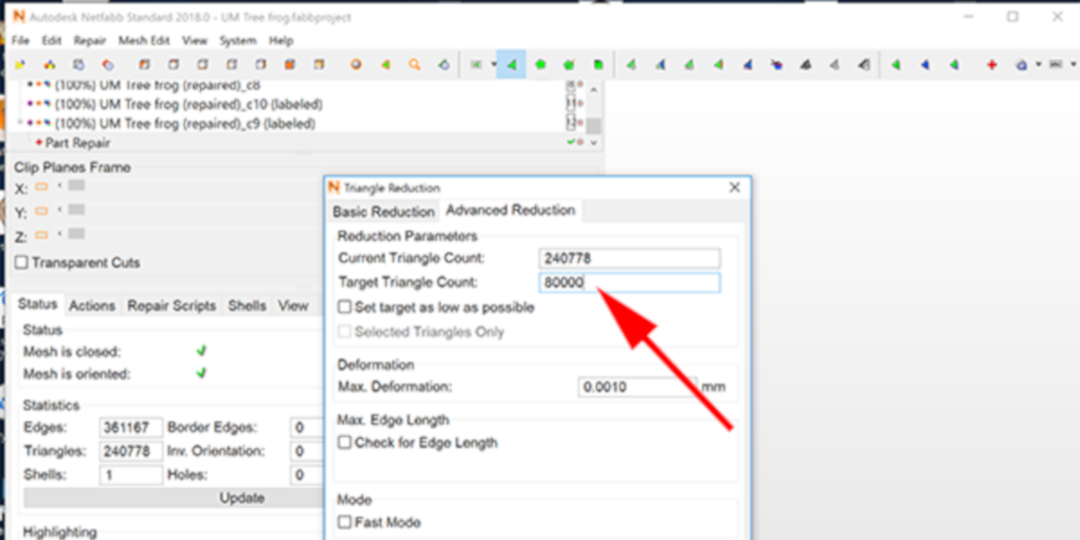
21. Enter a number for the target Triangle count. I generally enter 80K. Then click on Execute:
23. Click on another coded model and this time reduce the triangles to a target that is as low as possible. Netfabb will work to preserve the integrity of your mesh:
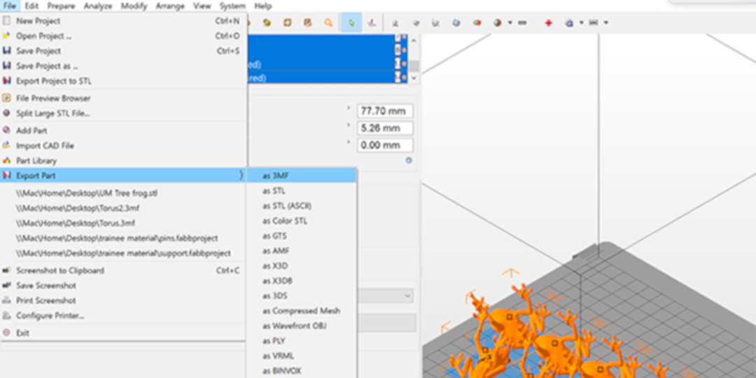
24. Select all your coded models and select Export part from the File menu. Export these models as 3MF:
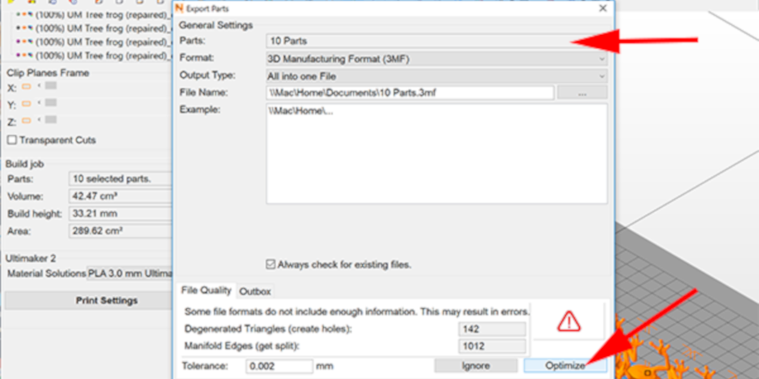
25. Name your file and set where you want to save it. Optimize, then click the OK button:
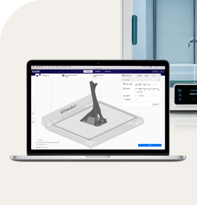
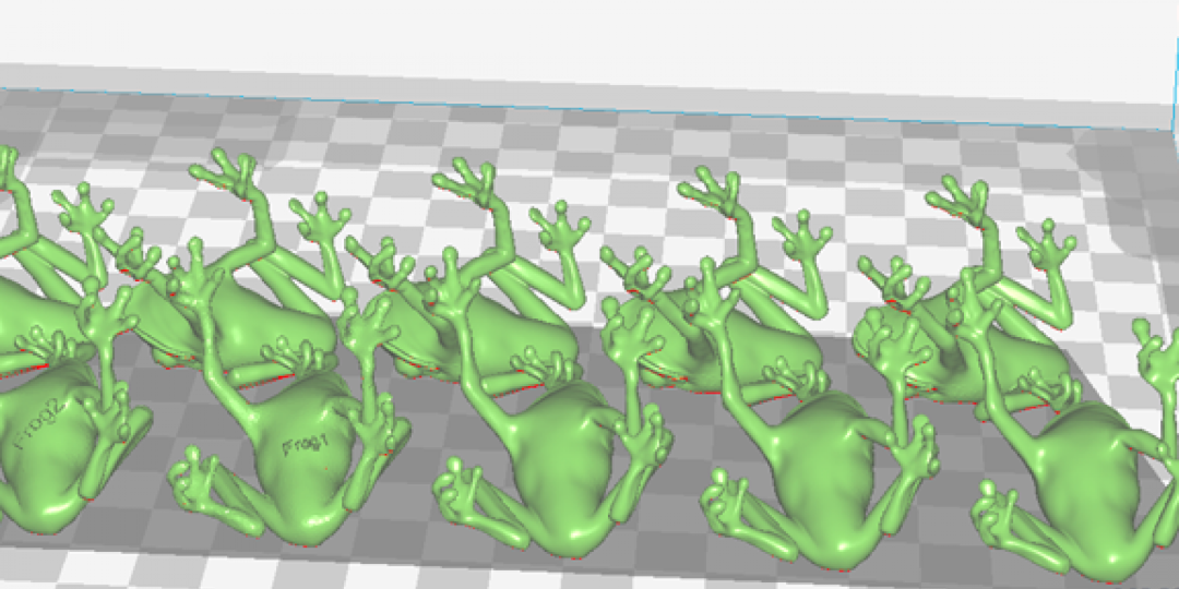
26. Now import the 3MF file into Cura and print:
What other tips and tricks did I learn?
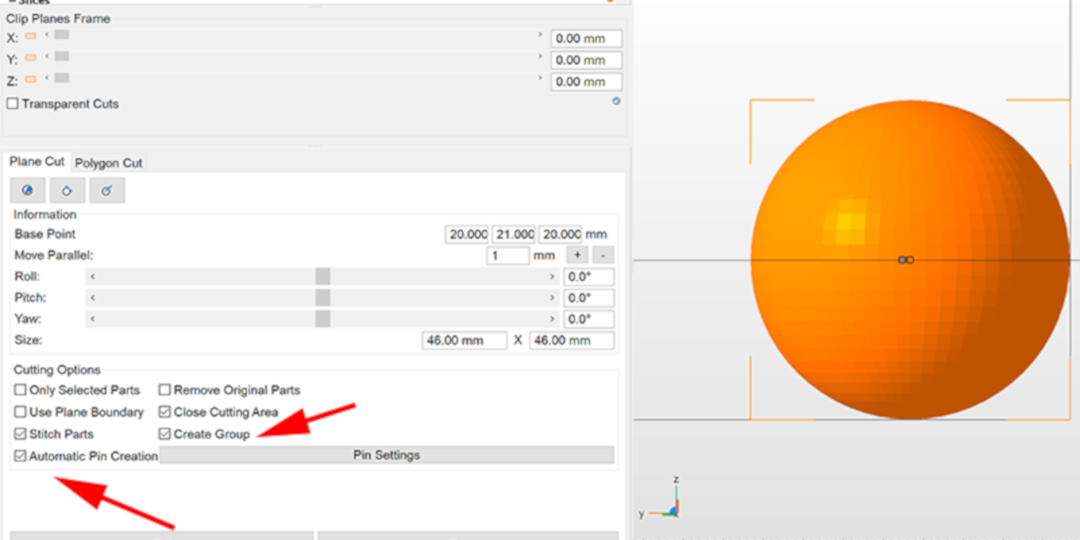
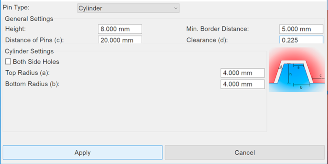
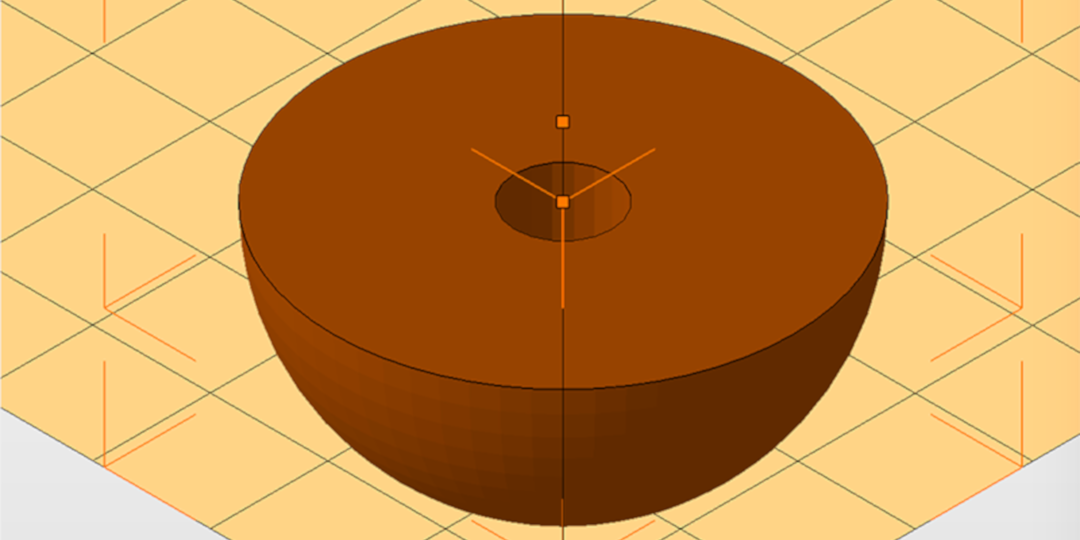
Here’s a fun one: adding pins to join parts. Import a part, cut it in two pieces, but before you click the cut button, enable Automatic Pin Creation and Create Group. Then click on Pin Settings. If you only want a pin in the center, set the Distance of pins to the radius. Make sure to set your tolerance: a pin with the same diameter as a hole with no tolerance won’t fit together. Also note that you can change the top and bottom radii of the pins to get a tapered pin.
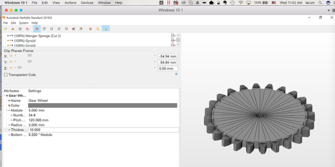
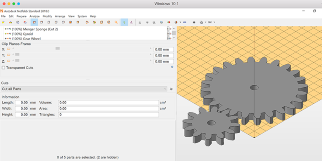
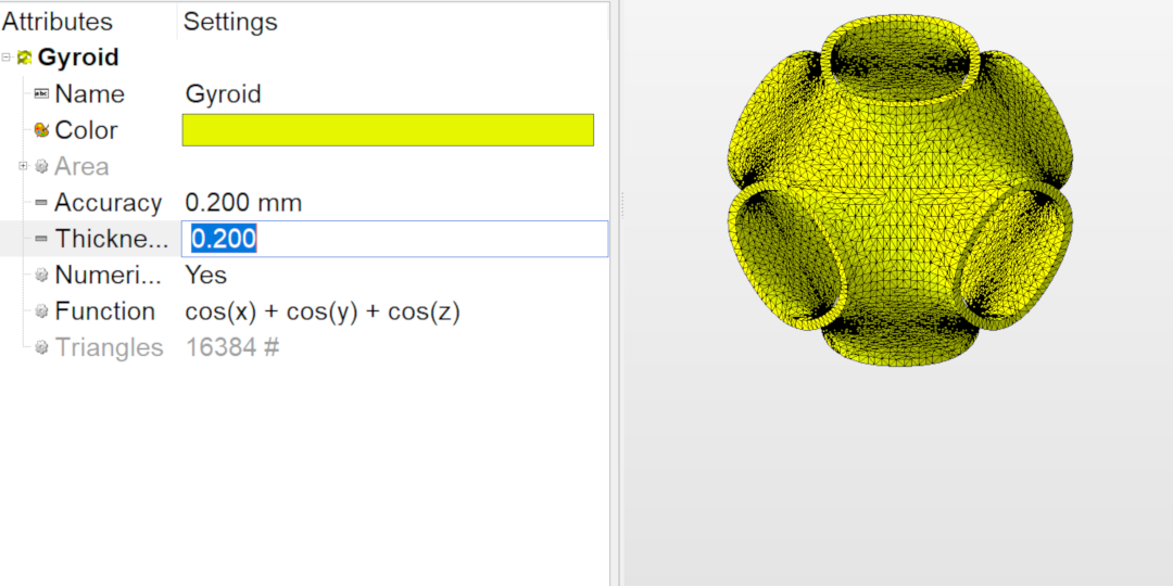
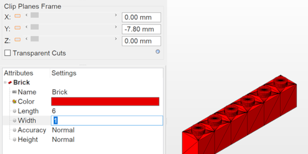
And there are quite a few hidden gems in the Part Library. You might expect the availability of basic primitive shapes, but you might be surprised to find mechanical parts like gears, mathematical functions, like gyroids, and a slew of random “design” parts that are parametrically driven.
Or create a custom configuration of a brick:
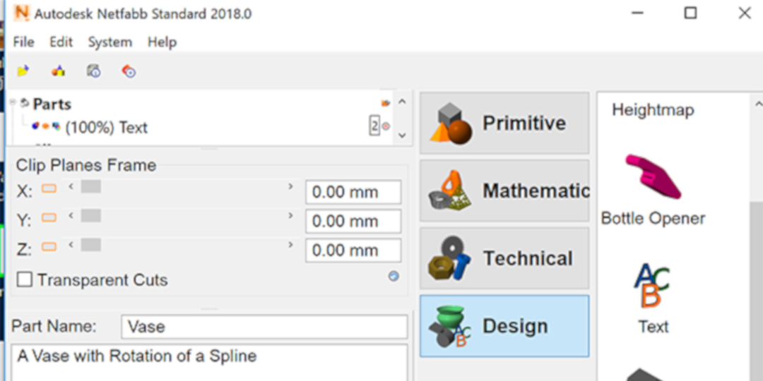
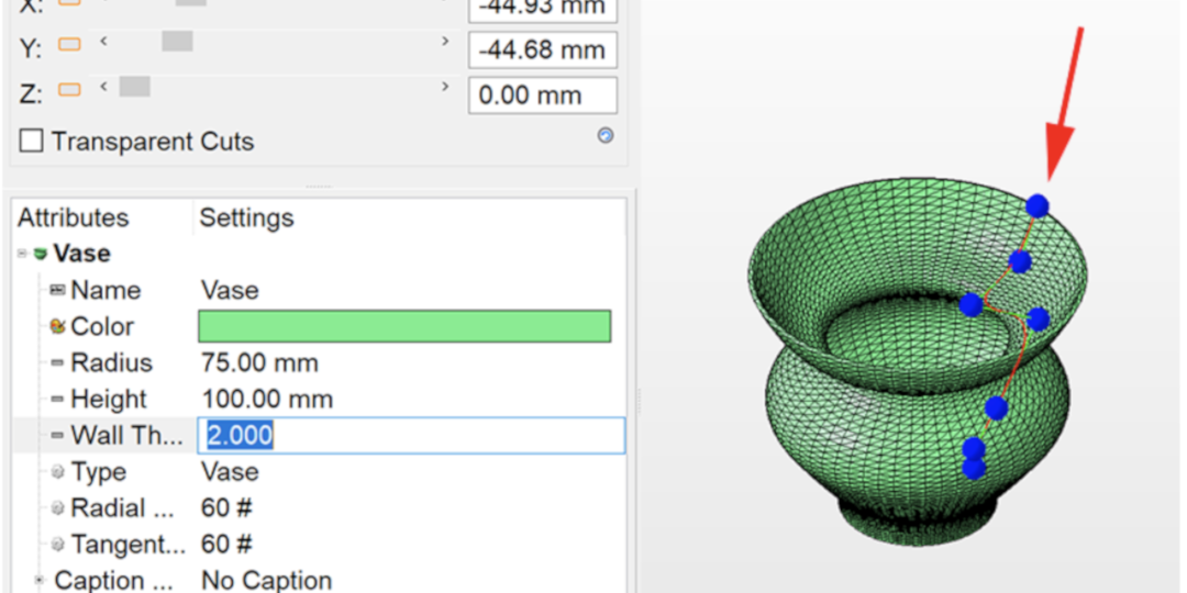
Move nodes around to create a custom vase:
It seems that every time I look deeper into the application, I find another handy surprise. I could spend hours exploring, creating and printing. Now if only Autodesk will reintroduce a mac version!
The frog STL used in this blog was created by Victor De Los Angeles of CuboDesigns.